Showing posts with label Physics. Show all posts

Monday, June 3, 2024

Laws of Motion

We saw that uniform motion needs the concept of velocity alone whereas non-uniform motion requires the concept of acceleration in addition. So far, we have not asked the question as to what governs the motion of bodies. In this chapter, we turn to this basic question.
Let us first guess the answer based on our common experience. To move a football at rest, someone must kick it. To throw a stone upwards, one has to give it an upward push. A breeze causes the branches of a tree to swing; a strong wind can even move heavy objects. A boat moves in a flowing river without anyone rowing it. Clearly, some external agency is needed to provide force to move a body from rest. Likewise, an external force is needed also to retard or stop motion. You can stop a ball rolling down an inclined plane by applying a force against the direction of its motion.
In these examples, the external agency of force (hands, wind, stream, etc) is in contact with the object. This is not always necessary. A stone released from the top of a building accelerates downward due to the gravitational pull of the earth. A bar magnet can attract an iron nail from a distance. This shows that external agencies (e.g. gravitational and magnetic forces ) can exert force on a body even from a distance.
In short, a force is required to put a stationary body in motion or stop a moving body, and some external agency is needed to provide this force. The external agency may or may not be in contact with the body. 

Sunday, June 2, 2024

Mechanical Properties of Solids at a Glance

1. Stress is the restoring force per unit area and strain is the fractional change in dimension. In general there are three types of stresses (a) tensile stress — longitudinal stress (associated with stretching) or compressive stress (associated with compression), (b) shearing stress, and (c) hydraulic stress. 

2. For small deformations, stress is directly proportional to the strain for many materials. This is known as Hooke’s law. The constant of proportionality is called modulus of elasticity. Three elastic moduli viz., Young’s modulus, shear modulus and bulk modulus are used to describe the elastic behaviour of objects as they respond to deforming forces that act on them.
A class of solids called elastomers does not obey Hooke’s law.

3. When an object is under tension or compression, the Hooke’s law takes the form
F/A = Y∆L/L
where ∆L/L is the tensile or compressive strain of the object, F is the magnitude of the applied force causing the strain, A is the cross-sectional area over which F is applied (perpendicular to A) and Y is the Young’s modulus for the object. The stress is F/A.

4. A pair of forces when applied parallel to the upper and lower faces, the solid deforms so that the upper face moves sideways with respect to the lower. The horizontal displacement ∆L of the upper face is perpendicular to the vertical height L. This type of deformation is called shear and the corresponding stress is the shearing stress. This type of stress is possible only in solids.
In this kind of deformation the Hooke’s law takes the form
F/A = G × ∆L/L

where ∆L is the displacement of one end of object in the direction of the applied force F, and G is the shear modulus.

5. When an object undergoes hydraulic compression due to a stress exerted by a surrounding fluid, the Hooke’s law takes the form
p = B (∆V/V), 
where p is the pressure (hydraulic stress) on the object due to the fluid, ∆V/V (the volume strain) is the absolute fractional change in the object’s volume due to that pressure and B is the bulk modulus of the object.

6. In the case of a wire, suspended from celing and stretched under the action of a weight (F) suspended from its other end, the force exerted by the ceiling on it is equal and opposite to the weight. However, the tension at any cross-section A of the wire is just F and not 2F. Hence, tensile stress which is equal to the tension per unit area is equal to F/A.

7. Hooke’s law is valid only in the linear part of stress-strain curve.

8. The Young’s modulus and shear modulus are relevant only for solids since only solids have lengths and shapes.

9. Bulk modulus is relevant for solids, liquid and gases. It refers to the change in volume when every part of the body is under the uniform stress so that the shape of the body remains unchanged. 

10. Metals have larger values of Young’s modulus than alloys and elastomers. A material with large value of Young’s modulus requires a large force to produce small changes in its length. 

11. In daily life, we feel that a material which stretches more is more elastic, but it a is misnomer. In fact material which stretches to a lesser extent for a given load is considered to be more elastic.

12. In general, a deforming force in one direction can produce strains in other directions also. The proportionality between stress and strain in such situations cannot be described by just one elastic constant. For example, for a wire under longitudinal strain, the lateral dimensions (radius of cross section) will undergo a small change, which is described by another elastic constant of the material (called Poisson ratio).

13. Stress is not a vector quantity since, unlike a force, the stress cannot be assigned a specific direction. Force acting on the portion of a body on a specified side of a section has a definite direction.

Friday, May 31, 2024

Ideal-gas Equation and Absolute Temperature

Ideal-gas Equation and Absolute Temperature

Liquid-in-glass thermometers show different readings for temperatures other than the fixed points because of differing expansion properties. A thermometer that uses a gas, however, gives the same readings regardless of which gas is used. Experiments show that all gases at low densities exhibit same expansion behaviour. The variables that describe the behaviour of a given quantity (mass) of gas are pressure, volume, and temperature (P, V, and T)(where T = t + 273.15; t is the temperature in °C). When temperature is held constant, the pressure and volume of a quantity of gas are related as pv = constant.

Fig. 1
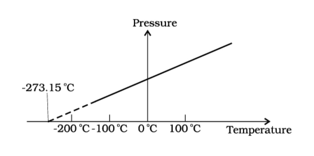
Pressure versus temperature of a low density gas kept at constant volume.  
This relationship is known as Boyle’s law, after Robert Boyle (1627–1691), the English Chemist who discovered it. When the pressure is held constant, the volume of a quantity of the gas is related to the temperature as V/T = constant. This relationship is known as Charles’ law, after French scientist Jacques Charles (1747–1823). Low-density gases obey these laws, which may be combined into a single relationship. Notice that since pV = constant and V/T = constant for a given quantity of gas, then pV/T should also be a constant. This relationship is known as ideal gas law. It can be written in a more general form that applies not just to a given quantity of a single gas but to any quantity of any low-density gas and is known as ideal-gas equation:
PV/T = µR
or PV = µRT ....... 1
where, µ is the number of moles in the sample of gas and R is called universal gas constant:
R = 8.31 J mol–1 K–1
In Eq. 1, we have learnt that the pressure and volume are directly proportional to temperature : PV ∝ T. This relationship allows a gas to be used to measure temperature in a constant volume gas thermometer. Holding the volume of a gas constant, it gives P ∝T. Thus, with a constant-volume gas thermometer, temperature is read in terms of pressure. A plot of pressure versus temperature gives a straight line in this case, as shown in Fig.1
However, measurements on real gases deviate from the values predicted by the ideal gas law at low temperature. But the relationship is linear over a large temperature range, and it looks as though the pressure might reach zero with decreasing temperature if the gas continued to be a gas. The absolute minimum temperature for an ideal gas, therefore, inferred by extrapolating the straight line to the axis, as in Fig. 10.3. This temperature is found to be 
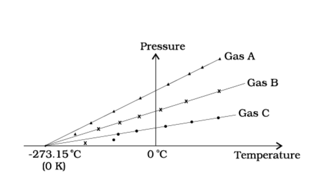
– 273.15 °C and is designated as absolute zero. Absolute zero is the foundation of the Kelvin temperature scale or absolute scale temperature named after the British scientist Lord Kelvin. On this scale, – 273.15 °C is taken as the zero point, that is 0 K (Fig. 2). 
  Fig.2 A plot of pressure versus temperature and extrapolation of lines for low density gases indicates the same absolute zero temperature.  


  Fig.3 Comparision of the Kelvin, Celsius and Fahrenheit temperature scales.  
  The size of unit in Kelvin and Celsius temperature scales is the same. So, temperature on these scales are related by
T = tC + 273.15      (3)

Sunday, March 26, 2023

Coulomb’s Law

Coulomb’s Law
Coulomb’s law is a quantitative statement about the force between two point charges. When the linear size of charged bodies are much smaller than the distance separating them, the size may be ignored and the charged bodies are treated as point charges. Coulomb measured the force between two point charges and found that it varied inversely as the square of the distance between the charges and was directly proportional to the product of the magnitude of the two charges and acted along the line joining the two charges. Thus, if two point charges q1, q2 are separated by a distance r in vacuum, the magnitude of the force (F) between them is given by 
F =|q1×q2|/r²
How did Coulomb arrive at this law from his experiments? Coulomb used a torsion balance* for measuring the force between two charged metallic spheres. When the separation between two spheres is much larger than the radius of each sphere, the charged spheres may be regarded as point charges.

Sunday, March 19, 2023

Basic Properties of Electric Charge

1.5 Basic Properties of Electric Charge
We have seen that there are two types of charges, namely positive and negative and their effects tend to cancel each other. Here, we shall now describe some other properties of the electric charge. 
If the sizes of charged bodies are very small as compared to the distances between them, we treat them as point charges. All the  charge content of the body is assumed to be concentrated at one point  in space.


1.5.1 Additivity of charges
We have not as yet given a quantitative definition of a charge; we shall follow it up in the next section. We shall tentatively assume that this can be done and proceed. If a system contains two point charges q1 and q2, the total charge of the system is obtained simply by adding algebraically q1 and q2 , i.e., charges add up like real numbers or they are scalars like the mass of a body. If a system contains n charges q1, q2, q3, …, qn, then the total charge of the system is q1 + q2 + q3 + … + qn . Charge has magnitude but no direction, similar to mass. However, there is one difference between mass and charge. Mass of a body is always positive whereas a charge can be either positive or negative. Proper signs have to be used while adding the charges in a system. For example, the  total charge of a system containing five charges +1, +2, –3, +4 and –5,  in some arbitrary unit, is (+1) + (+2) + (–3) + (+4) + (–5) = –1 in the  same unit.
1.5.2 Charge is conserved
We have already hinted to the fact that when bodies are charged by rubbing, there is transfer of electrons from one body to the other; no new charges are either created or destroyed. A picture of particles of electric charge enables us to understand the idea of conservation of charge. When we rub two bodies, what one body gains in charge the other body loses. Within an isolated system consisting of many charged bodies, due to interactions among the bodies, charges may get redistributed but it is found that the total charge of the isolated system is always conserved. Conservation of charge has been established experimentally.
It is not possible to create or destroy net charge carried by any isolated system although the charge carrying particles may be created or destroyed in a process. Sometimes nature creates charged particles: a neutron turns into a proton and an electron. The proton and electron thus created have equal and opposite charges and the total charge is zero before and after the creation. 
1.5.3 Quantisation of charge
Experimentally it is established that all free charges are integral multiples of a basic unit of charge denoted by e. Thus charge q on a body is always given by
q = ne
where n is any integer, positive or negative. This basic unit of charge is the charge that an electron or proton carries. By convention, the charge on an electron is taken to be negative; therefore charge on an electron is written as –e and that on a proton as +e. 
The fact that electric charge is always an integral multiple of e is termed as quantisation of charge. There are a large number of situations in physics where certain physical quantities are quantised. The quantisation of charge was first suggested by the experimental laws of electrolysis discovered by English experimentalist Faraday. It was experimentally demonstrated by Millikan in 1912. 
In the International System (SI) of Units, a unit of charge is called a coulomb and is denoted by the symbol C. A coulomb is defined in terms the unit of the electric current which you are going to learn in a subsequent chapter. In terms of this definition, one coulomb is the charge flowing through a wire in 1 s if the current is 1 A (ampere), (see Chapter 2 of Class XI, Physics Textbook , Part I). In this system, the value of the basic unit of charge is 
e = 1.602192 × 10⁻¹⁹ C
Thus, there are about 6 × 10¹⁸ electrons in a charge of –1C. In electrostatics, charges of this large magnitude are seldom encountered and hence we use smaller units 1 µC (micro coulomb) = 10–6 C or 1 mC (milli coulomb) = 10–3 C. 
If the protons and electrons are the only basic charges in the universe, all the observable charges have to be integral multiples of e. Thus, if a body contains n1 electrons and n2 protons, the total amount of charge on the body is n2 × e + n1 × (–e) = (n2 – n1) e. Since n1 and n2 are integers, their difference is also an integer. Thus the charge on any body is always an integral multiple of e and can be increased or decreased also in steps of e. 
The step size e is, however, very small because at the macroscopic level, we deal with charges of a few µC. At this scale the fact that charge of a body can increase or decrease in units of e is not visible. In this respect, the grainy nature of the charge is lost and it appears to be continuous.
This situation can be compared with the geometrical concepts of points and lines. A dotted line viewed from a distance appears continuous to us but is not continuous in reality. As many points very close to each other normally give an impression of a continuous line, many  small charges taken together appear as a continuous charge  distribution.
At the macroscopic level, one deals with charges that are enormous compared to the magnitude of charge e. Since e = 1.6 × 10⁻¹⁹ C, a charge of magnitude, say 1 µC, contains something like 1013 times the electronic charge. At this scale, the fact that charge can increase or decrease only in units of e is not very different from saying that charge can take continuous values. Thus, at the macroscopic level, the quantisation of charge has no practical consequence and can be ignored. However, at the microscopic level, where the charges involved are of the order of a few tens or hundreds of e, i.e., they can be counted, they appear in discrete lumps and quantisation of charge cannot be ignored. It is the magnitude of scale involved that is very important.

Wednesday, August 31, 2022

Work And Energy

This video lecture consists of 
1. Definition of Work
2. Dimension of work
3. Unit of work
4. Definition of energy
5. Types of mechanical energy
6. Conservation of energy 

Thursday, January 6, 2022

Electromagnetic Waves

Electromagnetic Spectrum


At the time Maxwell predicted the existence of electromagnetic waves, the only familiar electromagnetic waves were the visible light waves. The existence of ultraviolet and infrared waves was barely established. By the end of the nineteenth century, X-rays and gamma rays had also been discovered. We now know that, electromagnetic waves include visible light waves, X-rays, gamma rays, radio waves, microwaves, ultraviolet and infrared waves. The classification of em waves according to frequency is the electromagnetic spectrum. There is no sharp division between one kind of wave and the next. The classification is based roughly on how the waves are produced and/or detected.


(Figure The electromagnetic spectrum, with common names for various part of it. The various regions do not have sharply defined boundaries.)


We briefly describe these different types of electromagnetic waves, in order of decreasing wavelengths.


Radio waves


Radio waves are produced by the accelerated motion of charges in conducting wires. They are used in radio and television communication systems. They are generally in the frequency range from 500 kHz to about 1000 MHz. The AM (amplitude modulated) band is from 530 kHz to 1710 kHz. Higher frequencies upto 54 MHz are used for short wave bands. TV waves range from 54 MHz to 890 MHz. The FM (frequency modulated) radio band extends from 88 MHz to 108 MHz. Cellular phones use radio waves to transmit voice communication in the ultrahigh frequency (UHF) band. How these waves are transmitted and received is described in Chapter 15.


Microwaves


Microwaves (short-wavelength radio waves), with frequencies in the gigahertz (GHz) range, are produced by special vacuum tubes (called klystrons, magnetrons and Gunn diodes). Due to their short wavelengths, they are suitable for the radar systems used in aircraft navigation. Radar also provides the basis for the speed guns used to time fast balls, tennis- serves, and automobiles. Microwave ovens are an interesting domestic application of these waves. In such ovens, the frequency of the microwaves is selected to match the resonant frequency of water molecules so that energy from the waves is transferred efficiently to the kinetic energy of the molecules. This raises the temperature of any food containing water.


Microwave oven


The spectrum of electromagnetic radiation contains a part known as microwaves. These waves have frequency and energy smaller than visible light and wavelength larger than it. What is the principle of a microwave oven and how does it work?Our objective is to cook food or warm it up. All food items such as fruit, vegetables, meat, cereals, etc., contain water as a constituent. Now, what does it mean when we say that a certain object has become warmer? When the temperature of a body rises, the energy of the random motion of atoms and molecules increases and the molecules travel or vibrate or rotate with higher energies. The frequency of rotation of water molecules is about

2.45 gigahertz (GHz). If water receives microwaves of this frequency, its molecules absorb this radiation, which is equivalent to heating up water. These molecules share this energy with neighbouring food molecules, heating up the food.

One should use porcelain vessels and not metal containers in a microwave oven because of the danger of getting a shock from accumulated electric charges. Metals may also melt from heating. The porcelain container remains unaffected and cool, because its large molecules vibrate and rotate with much smaller frequencies, and thus cannot absorb microwaves. Hence, they do not get heated up.

Thus, the basic principle of a microwave oven is to generate microwave radiation of appropriate frequency in the working space of the oven where we keep food. This way energy is not wasted in heating up the vessel. In the conventional heating method, the vessel on the burner gets heated first, and then the food inside gets heated because of transfer of energy from the vessel. In the microwave oven, on the other hand, energy is directly delivered to water molecules which is shared by the entire food.


Infrared waves


Infrared waves are produced by hot bodies and molecules. This band lies adjacent to the low-frequency or long-wave length end of the visible spectrum. Infrared waves are sometimes referred to as heat waves. This is because water molecules present in most materials readily absorb infrared waves (many other molecules, for example, CO2, NH3, also absorb infrared waves). After absorption, their thermal motion increases, that is, they heat up and heat their surroundings. Infrared lamps are used in physical therapy. Infrared radiation also plays an important role in maintaining the earth’s warmth or average temperature through the greenhouse effect. Incoming visible light (which passes relatively easily through the atmosphere) is absorbed by the earth’s surface and re-radiated as infrared (longer wavelength) radiations. This radiation is trapped by greenhouse gases such as carbon dioxide and water vapour. Infrared detectors are used in Earth satellites, both for military purposes and to observe growth of crops. Electronic devices (for example semiconductor light emitting diodes) also emit infrared and are widely used in the remote switches of household electronic systems such as TV sets, video recorders and hi-fi system.


Visible rays


It is the most familiar form of electromagnetic waves. It is the part of the spectrum that is detected by the human eye. It runs from about 4 × 10¹⁴ Hz to about 7 × 10¹⁴ Hz or a wavelength range of about 700 – 400 nm. Visible light emitted or reflected from objects around us provides us information about the world. Our eyes are sensitive to this range of wavelengths. Different animals are sensitive to different range of wavelengths. For example, snakes can detect infrared waves, and the ‘visible’ range of many insects extends well into the utraviolet.


Ultraviolet rays


It covers wavelengths ranging from about 4 × 10‐⁷ m (400 nm) down to 6 × 10‐¹⁰m (0.6 nm). Ultraviolet (uv) radiation is produced by special lamps and very hot bodies. The sun is an important source of ultraviolet light. But fortunately, most of it is absorbed in the ozone layer in the atmosphere at an altitude of about 40 – 50 km. uv light in large quantities has harmful effects on humans. Exposure to UV radiation induces the production of more melanin, causing tanning of the skin. UV radiation is absorbed by ordinary glass. Hence, one cannot get tanned or sunburn through glass windows.

Welders wear special glass goggles or face masks with glass windows to protect their eyes from large amount of UV produced by welding arcs. Due to its shorter wavelengths, UV radiations can be focussed into very narrow beams for high precision applications such as LASIK (Laser-assisted in situ keratomileusis) eye surgery. UV lamps are used to kill germs in water purifiers. 

Ozone layer in the atmosphere plays a protective role, and hence its depletion by chlorofluorocarbons (CFCs) gas (such as freon) is a matter of international concern. 


X-rays


Beyond the uv region of the electromagnetic spectrum lies the x-ray region. We are familiar with x-rays because of its medical applications. It covers wavelengths from about 10‐⁸ m (10 nm) down to 10‐¹⁰ m 

(10‐⁴ nm). One common way to generate X-rays is to bombard a metal target by high energy electrons. X-rays are used as a diagnostic tool in medicine and as a treatment for certain forms of cancer. Because x-rays damage or destroy living tissues and organisms, care must be taken to avoid unnecessary or over exposure. 


Gamma rays


They lie in the upper frequency range of the electromagnetic spectrum and have wavelengths of from about 10‐¹⁰m to less than 10‐¹⁰m. This high frequency radiation is produced in nuclear reactions and 

also emitted by radioactive nuclei. They are used in medicine to destroy cancer cells. 

Table summarises different types of electromagnetic waves, their production and detections. As mentioned earlier, the demarcation between different regions is not sharp and there are overlaps.

Sunday, December 26, 2021

Electric Generator

Electric Generator


Uses and Working Principle


Based on the phenomenon of electromagnetic induction, the experiments studied above generate induced current, which is usually very small. This principle is also employed to produce large currents for use in homes and industry. In an electric generator, mechanical energy is used to rotate a conductor in a magnetic field to produce electricity.


General Construction of an Electric Generator


An electric generator, as shown in Fig, consists of a rotating rectangular coil ABCD placed between the two poles of a permanent magnet. The two ends of this coil are connected to the two rings R1 and R2. The inner side of these rings are made insulated. The two conducting stationary brushes B1 and B2 are kept pressed separately on the rings R1 and R2, respectively. The two rings R1 and R2 are internally attached to an axle. The axle may be mechanically rotated from outside to rotate the coil inside the magnetic field. Outer ends of the two brushes are connected to the galvanometer to show the flow of current in the given external circuit.


Working of Electric Generator


When the axle attached to the two rings is rotated such that the arm AB moves up (and the arm CD moves down) in the magnetic field produced by the permanent magnet. Let us say the coil ABCD is rotated clockwise in the arrangement shown in Fig.

Figure Illustration of the principle of electric generator

By applying Fleming’s right-hand rule, the induced currents are set up in these arms along the directions AB and CD. Thus an induced current flows in the direction ABCD. If there are larger numbers of turns in the coil, the current generated in each turn adds up to give a large current through the coil. This means that the current in the external circuit flows from B2 to B1.

After half a rotation, arm CD starts moving up and AB moving down. As a result, the directions of the induced currents in both the arms change, giving rise to the net induced current in the direction DCBA. The current in the external circuit now flows from B1 to B2. Thus after every half rotation the polarity of the current in the respective arms changes. Such a current, which changes direction after equal intervals of time, is called an alternating current (abbreviated as AC). This device is called an AC generator.

To get a direct current (DC, which does not change its direction with time), a split-ring type commutator must be used. With this arrangement, one brush is at all times in contact with the arm moving up in the field, while the other is in contact with the arm moving down. We have seen the working of a split ring commutator in the case of an electric motor (see Fig.). Thus a unidirectional current is produced. The generator is thus called a DC generator.

The difference between the direct and alternating currents is that the direct current always flows in one direction, whereas the alternating current reverses its direction periodically. Most power stations constructed these days produce AC. 


Characteristics of Produced A.C. in India


In India, the AC changes direction after every 1/100 second, that is, the frequency of AC is 50 Hz. An important advantage of AC over DC is that electric power can be transmitted over long distances without much loss of energy.

Wednesday, December 23, 2020

Electricity

Q.No.1. What does an electric circuit mean ?
Answer
An electric circuit means a continuous and closed path of an electric current.
Q.No. 2. Define the unit of current.
Answer
The electric current is expressed by a unit called ampere (A), named after the French scientist, Andre-Marie Ampere . One ampere is constituted by the flow of one coulomb of charge per second, that is, 1 A = 1 C/1 s.
Q.No. 3. Calculate the number of electrons constituting one coulomb of charge.
Answer
We know that
1.6×10-¹⁹ coulomb charge = 1 Electron.
or, 1 coulomb charge = 1÷(1.6×10-¹⁹) Electrons.
or, 1 coulomb charge = 6×10¹⁸ Electrons.
Q.No.1. Name a device that helps to maintain a potential difference across a conductor.
Answer 
Battery or a combination of cells helps to maintain a potential difference across a conductor. 
2. What is meant by saying that the potential difference between two points is 1 V?
Answer 
One volt is the potential difference between two points in a current carrying conductor when 1 joule of work is done to move a charge of 1 coulomb from one point to the other.
Therefore,
1 volt = 1 joule/1 coulomb
1 volt = 1joule per coulomb. 
1 V = 1 J/C.
3. How much energy is given to each coulomb of charge passing through a 6 V battery?
Answer 
Work done = Potential difference×Charge 
or, Work done = 6×1
or, Work done = 6 joule.
Continue .....

Saturday, October 12, 2019

4.7 Ampere's Circuital Law

Subject: Physics

Class XII

Chapter: 4. Moving Charges and Magnetism


Ampere's Law
 "The integral of magnetic field around a closed path is equal to the product of absolute permeability and total current passing through it."

Mathematical form
∮B.dl = μ₀.I

Here,
B = Magnetic field
dl = Current element
μ₀ = Absolute Permeability
I = Current passing through it

Proof
Consider about an infinitesimal carrying conductor through which I current passing is passing. Magnetic field lines are produced around the conductor as the form of concentric circles.
Magnetic field at a distance due to this infinitesimal conductor. 
B = μ₀.2I/4πa ................... (i)

Now consider about a circle of radius a having a current element dl.
Both B and dl have same direction because B is along the the tangent of circle.
Hence,
B.dl = Bdlcosθ = Bdlcos0⁰ = Bdl

Now integrate the closed path
∮B.dl = ∮Bdl .............. (ii)
Now putting the value of B
∮B.dl = μ₀.2Idl/4πa
∮B.dl  = μ₀.2I/4πa∮dl
For complete cirecle
∮dl = 2πa
∮B.dl  = μ₀.2I.2πa/4πa
∮B.dl = μ₀.I
Proved

Friday, October 11, 2019

4.6 Magnetic Field on the Axis of Circular Current Loop

Subject: Physics

Class : XII

Chapter 4. Moving Charges and Magnetism

4.6 Magnetic Field on the Axis of Circular Current Loop


Consider about a circular loop of radius R carrying the current I. The loop is placed in the y-z plane with its centre at the origin O. The x axis is the axis of the loop. There is a point P at a distance x from the centre of the loop at which magnetic field is to be determined.

Mathematical Calculation

dl is the conducting element of the loop.
The magnitude of dB of the magnetic field due to dl is according to Biot-Savart Law
dB = 𝝁₀I|dlxr|/4𝜋r³
Now 
r² = x² + R²
Any element to loop will be perpendicular to the displacement vector r from dl to the axial point P is in the x-y plane.
Hence,
|dlxr| = rdl
dB = 𝝁₀Idlr/4𝜋r³ ............... (i)
Now putting the value of r
dB = 𝝁₀Idl/4𝜋(x² + R²)
The direction of dB is perpendicular to the plane formed by dl and r.
It has an x- component dBₓ and a component perpendicular to x-axis dB⫡.
When the components perpendicular to the x- axis are summed over, they cancel out.
Only the x component survives.
dBₓ = dBcos𝜃
From figure 
cos𝜃 = R/√(x² + R²) ............. (ii)
Now from eqn. no. (i) and (ii)
dBₓ = 𝝁₀IdlR/4𝜋(x² + R²)³/²
For whole circular loop
dl = 2𝜋R
Magnetic field at P due to entire circular loop
= B = Bₓi = 𝝁₀IR²/2𝜋(x² + R²)³/²i
Field at the centre of the loop. Here x = 0
B₀ = 𝝁₀I/2R

The direction of the magnetic field is determined by the help of 
Fleming Right Hand Thumb rule.

Saturday, October 5, 2019

4.4.2 Cyclotron Class XII.

The Cyclotron is a machine which is used to accelerate the charged particles.
This machine was invented by E.O. Lowrence and M.S Livingston. 

Construction

It has two hollow chambers of D shaped is called dees. There is some gap between the dees in which source of positive particles are kept. These dees are connected by high frequent oscillator which provides high frequent electric field between the gap of dees. This machine is placed between the two powerful electromagnetic poles.

Working Principle

Positive charged particles accelerated from D1 to D2 when D1 and D2 are positive and negative respectively. In D2 charged particles accelerated perpendicular to the magnetic field.

The schematic figure of Cyclotron is drawn below.


The charged particles move in a semi circular path perpendicular to the magnetic field.
Let the time taken to complete one revolution is T.
T = 2πm/qB
Frequency = 1/T
= qB/2πm
During the circular motion of charged particles.
mv²/r = qvB
v = qBr/m

Kinetic Energy = mv²/2
Now, putting the value of v.
Kinetic Energy = q²B²r²/2m.
Time of revolution is independent of speed of particles and radius of trajectory.

Uses of Cyclotron are as follow

1. Uses in the nuclear reactor plant
2. To implant ions into solids
3. To synthesis materials
4. To produce radio active substances in the hospital.

Wednesday, October 2, 2019

4. Moving Charges and Magnetism

Magnetic Field

Region around a current carrying conductor in which electro-magnetism effect is produced, is said to be Magnetic Field.

It is generally denoted by B. Magnetic field is a vector quantity. The dimension of magnetic field is [MA⁻¹T⁻²]. The SI unit of magnetic field is NA⁻¹m⁻¹ or Tesla.

B = Fm/qvsinθ

Here,
Fm = Magnetic Force
q = Magnitude of the charge
v = Velocity of the charge
θ = Angle between velocity and magnetic force.

Magnetic field vertically upward and downward in a plane are generally denoted by conventional sign (.) and (x) respectively. 

Total Magnetic field from different sources is the vector sum of the different magnetic field.
Therefore,

B = B1 + B2 + B3 + ...................... 
Super position principle is used during the sum of magnetic field.

Lorentz Force

The field in which both electric and magnetic field are in existence, the total force experienced by charge q due to motion is said to be Lorentz Force.

Lorentz Force = Force on charge due to electric field + Force on charge due to Magnetic field
F = Fe + Fm
Here,
F = Lorentz Force
Fe = Electric Force
Fm = Magnetic Force

Therefore,
Lorentz Force = F = qE + qvBsinθ

Special Cases of Magnetic Force

Magnetic Force = Fm = qvBsinθ
Case I
When θ = 0⁰ or 180⁰
Fm = 0
Charge will be moved either parallel or antiparallel of magnetic field.

Case II

When  θ = 90⁰ 
Fm = qvB
Charge will be moved along the perpendicular direction of magnetic field.

Magnetic Force on a current carryin conductor

                 Consider about a conductor which is placed in a magnetic field B along z axis. The direction of the magnetic field is along x axis. So that magnetic force will be along y axis according to Fleming's left hand rule.
                   We know that a large numbers of electrons are present in free state in a conductor which move opposite of current with drift velocity.

Mathematical Calculation


Let the length of the conductor = l
cross - sectional area of the conductor = A
drift velocity = v
current = I
charge = -e
No. of electrons per unit volume of the conductor = n

Now, according to Lorentz Magnetic Force
Fm = -evBsinθ
Now consider a small length dl.

Volume of conductor for this length = Adl
No. of electrons = nAdl
Charge = -enAdl

Magnetic Force for this length 
dFm = -enAdlvBsinθ

drift velocity for dl = v = -dl/dt             (The direction of dl is opposite to drift velocity)

Therefore,
dFm = -enAdlBsinθ.-dl/dt ---------------- (i)

enAdl/dt = I

Now, from (i)

dFm = I(dlxB)

For whole conductor

Fm = IlBsinθ

Direction of Fm, I and B are determined by Fleming's left hand rule.

Special Cases

Case I

When θ = 0⁰ or 180⁰
Charged particles move either parallel or anti parallel of magnetic field.

Case II

When θ = 90⁰ 

Charged particles move along the perpendicular of magnetic field.

Under this circumstances the charged particles move in circular path.


                  Consider about a charged particles of mass m and charge q moves in a circular path of radius r.

Centripetal Force experienced by the particle = mv²/r

Magnetic Force = qvB

qvBsinθ = mv²/r

r = mv/qB

Let the charged particle takes T time to move one rotation.
Therefore,
T = 2πr/v
Now putting the value of r
T = 2πm/qB

Frequency ν = 1/T = qB/2πm

Case III

When θ is other than 0⁰, 90⁰ or 180⁰

Let the angle be θ 

Magnetic field B is along x axis, current is along z axis and magnetic force Fm is along y axis.

Under this circumstances the charged particle moves in hellical path.


Vertical Components of drift velocity of charged particle = vsinθ
Horizontal Components of drift velocity of charged particle = vcosθ

Particle along vertical components moves along circular path.

Centripetal Force = m(vsinθ)²/r
Magnetic Force = qBvsinθ

Centripetal Force = Magnetic Force
r = mvsinθ/qB

T = 2πr/ vsinθ

Now putting the value of r

T = 2πm/qB

Frequency ν = 1/T = qB/2πm

Motion in Combined Electric and Magnetic Field

Consider about a charge q moves in a field in which both electric and magnetic field are perpendicular to each other.

Electric force acts along electric field and magnetic force opposite to electric force. Direction of magnetic field is determined by Fleming's right hand rule.

Mathematical Calculation


Fe = Fb

qE = qvB.sin90⁰
qE = qvB
v = qE/qB
v = E/B

Magnetic Field due to a current element, Biot Savart Law

Biot Savart Law states that 
"The magnitude of the magnetic field is proportional to the current, the element length and inversely proportional to the square the distance of the point from current element at which magnetic field is determined. The direction of the magnetic field is perpendicular to the plane containing element length and distance."

          Consider about a finite conductor XY carrying current I. dl is the current element. There is a point P at a distance r from the current element. At this point magnetic field dB is to be determined. The angle between dl and displacement vector r is θ.

The relevant figure is drawn below


Now according to Biot Savart Law

dB∝ Idlxr/r³
dB = 𝛍ₒIdlxr/4𝛑r³

Here 
𝛍ₒ/4𝛑 is a constant of proportionality ( The medium is vacuum)

Therefore, magnitude of the magnetic field
।dB। = 𝛍ₒIdlsinθ/4𝛑r²

The value of 𝛍ₒ/4𝛑 = 10⁻⁷ Tm/A
𝛍ₒ is the permeability of free space or vacuum.

There are some similarities, as well as differences, between Biot Savart's Law and Coulomb's Law. Which are as follows

1. Both depend inversely on the square of distance from the source of interest.
2.The principle of superposition applies to both magnetic and electric fields.
3. Both magnetic field and electric field is linear to their sources Idl (current element) and q (source of electric charge) respectively.
4. The electric field is produced by scalar source q (electric charge) whereas magnetic field is produced by vector source Idl (current element)
5. The electric field is along the displacement vector whereas magnetic field is perpendicular to the plane containing the displacement vector r and current element Idl.
6. The magnetic field at any point in the direction of dl is zero.

Relation between permitivity of free space (𝛆ₒ) and permeability of free space (𝛍ₒ) and speed of light (c).

𝛆ₒ𝛍ₒ = 4𝛑𝛆ₒ.𝛍ₒ/4𝛑

= 10⁻⁷/9x10⁹
= 1/9x10¹⁶
= 1/(3x10⁸)²
= 1/c²
Chapter 4 Class XII Moving Charges and Magnetism

Recently Added

Straight Line

  Slope of a Line A line in a coordinate plane forms two angles with the x-axis, which are supplementary.   The angle (say) θ made by the li...

Available Educational Materials