Electric Generator
Uses and Working Principle
Based on the phenomenon of electromagnetic induction, the experiments studied above generate induced current, which is usually very small. This principle is also employed to produce large currents for use in homes and industry. In an electric generator, mechanical energy is used to rotate a conductor in a magnetic field to produce electricity.
General Construction of an Electric Generator
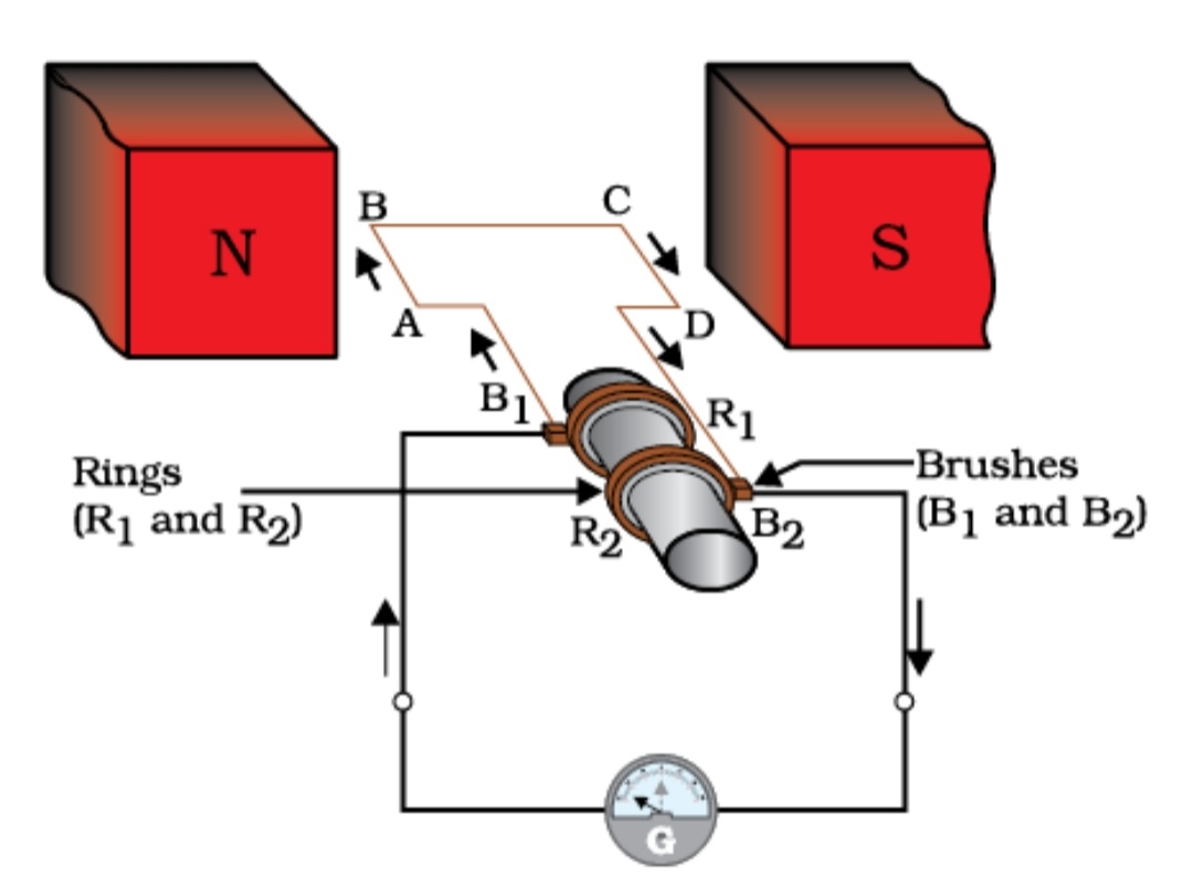
An electric generator, as shown in Fig, consists of a rotating rectangular coil ABCD placed between the two poles of a permanent magnet. The two ends of this coil are connected to the two rings R1 and R2. The inner side of these rings are made insulated. The two conducting stationary brushes B1 and B2 are kept pressed separately on the rings R1 and R2, respectively. The two rings R1 and R2 are internally attached to an axle. The axle may be mechanically rotated from outside to rotate the coil inside the magnetic field. Outer ends of the two brushes are connected to the galvanometer to show the flow of current in the given external circuit.
Working of Electric Generator
When the axle attached to the two rings is rotated such that the arm AB moves up (and the arm CD moves down) in the magnetic field produced by the permanent magnet. Let us say the coil ABCD is rotated clockwise in the arrangement shown in Fig.
Figure Illustration of the principle of electric generator
By applying Fleming’s right-hand rule, the induced currents are set up in these arms along the directions AB and CD. Thus an induced current flows in the direction ABCD. If there are larger numbers of turns in the coil, the current generated in each turn adds up to give a large current through the coil. This means that the current in the external circuit flows from B2 to B1.
After half a rotation, arm CD starts moving up and AB moving down. As a result, the directions of the induced currents in both the arms change, giving rise to the net induced current in the direction DCBA. The current in the external circuit now flows from B1 to B2. Thus after every half rotation the polarity of the current in the respective arms changes. Such a current, which changes direction after equal intervals of time, is called an alternating current (abbreviated as AC). This device is called an AC generator.
To get a direct current (DC, which does not change its direction with time), a split-ring type commutator must be used. With this arrangement, one brush is at all times in contact with the arm moving up in the field, while the other is in contact with the arm moving down. We have seen the working of a split ring commutator in the case of an electric motor (see Fig.). Thus a unidirectional current is produced. The generator is thus called a DC generator.
The difference between the direct and alternating currents is that the direct current always flows in one direction, whereas the alternating current reverses its direction periodically. Most power stations constructed these days produce AC.
Characteristics of Produced A.C. in India
In India, the AC changes direction after every 1/100 second, that is, the frequency of AC is 50 Hz. An important advantage of AC over DC is that electric power can be transmitted over long distances without much loss of energy.
No comments:
Post a Comment